Starting Methods of
Single Phase Motor
There
are different methods to start the 1-ϕ motors, they are as follows:
1- Split
Phase or Resistance Start
2- Capacitor
Start
3- Permanent
Split Capacitor
4- Capacitor
Start Capacitor Run
5- Electronic
Starter for Single Phase Motor
Resistance start motor
A resistance start motor is a
split-phase induction motor with a starter inserted in series with the startup
winding, creating reactance. This added starter provides assistance in the
starting and initial direction of rotation.

Capacitor start motor

Schematic
of a capacitor start motor.
A capacitor start motor is a
split-phase induction motor with a starting capacitor inserted in series with the startup
winding, creating an LC
circuit which
produces a greater phase shift (and so, a much greater starting torque) than
both split-phase and shaded pole motors.
Permanent-split capacitor motor
Another variation is the permanent-split capacitor (or PSC)
motor.Also known as a capacitor-run motor, this type of motor uses a
non-polarized capacitor with a high voltage rating to generate an electrical
phase shift between the run and start windings. PSC motors are the dominant
type of split-phase motor in Europe and much of the world, but in North
America, they are most frequently used in variable torque applications (like
blowers, fans, and pumps) and other cases where variable speeds are desired
.
A capacitor with a relatively
low capacitance, and relatively high voltage rating, is connected in series
with the start winding and remains in the circuit during the entire run
cycle.Like other split-phase motors, the main winding is used with a smaller
start winding, and rotation is changed by reversing the connection between the
main winding and the start circuit. There are significant differences, however;
the use of a speed sensitive centrifugal switch requires that other split-phase
motors must operate at, or very close to, full speed. PSC motors may operate
within a wide range of speeds, much lower than the motor's electrical speed.
Also, for applications like automatic door openers that require the motor to
reverse rotation often, the use of a mechanism requires that a motor must slow
to a near stop before contact with the start winding is re-established. The
'permanent' connection to the capacitor in a PSC motor means that changing
rotation is instantaneous.
Three-phase motors can be
converted to PSC motors by making common two windings and connecting the third
via a capacitor to act as a start winding. However, the power rating needs to
be at least 50% larger than for a comparable single-phase motor due to an
unused winding.
Capacitor start - capacitor run induction motor

A Capacitor Start Motor not only switches out the capacitor when up to speed, but also switches out the starting winding which is in series with the start capacitor. Capacitor Start motors have very high starting torque for a single phase AC motor. The same is true for a capacitor start / capacitor run motor with a centrifugal switch. In this case, the run capacitor is a different value and just provides some additional phase lag especially to help the motor maintain speed under load, and improve the power factor. A Capacitor start/run motor without a centrifugal switch has a lower starting torque, but good performance under load, and again, an improved power factor.
Protection Scheme of Single phase Induction Motor
The starter is a device which is used for switching and protecting the electric motor from the dangerous overloads by tripping. It reduces the starting current to the AC induction motors and also reduces the motor torque.
Electronic Starter Circuit Working
Electronic starter is used for motor protection from overload and short-circuit conditions. A current sensor in the circuit is used to limit the current drawn by the motor because in a few cases such as failure of the bearing, pump defect or any other reason, the current drawn by the motor exceeds its normal rated current. In these conditions the current sensor trips the circuit for protecting the motor. The electronic starter for the motor circuit block diagram is shown below.
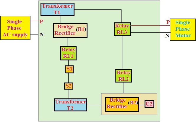
Electronic Starter Circuiy
Switch S1 is used for switching ON the supply through transformer T2 and N/C contacts of the relay RL1. The DC voltage developed across the capacitor C2 through the bridge rectifier will energize the relay RL2. With the energization of the relay RL2, the voltage developed across the C2 energizes the relay RL3 and thus, supply is given to the motor. If the motor draws overcurrent, then the voltage developed across the secondary of the transformerT2 energizes the relay RL1 to trip the relays RL2 and RL3.
Soft Start of Induction Motor by ACPWM
The proposed system is intended to offer soft start of the single phase induction motor using a PWM sinusoidal voltage while starting the motor. This system avoids the frequently used TRIAC-phase-angle control drives and provides variable AC voltage during the starting of the single phase induction motor. Similar to the TRIAC control method, the voltage is varied from zero to maximum during the start in a very small span of time.
As, in this technique we use the PWM technique that produces much lower high order harmonics. In this project, the mains AC voltage is directly modulated using a very less number of active and passive power components. Hence, it does not require any converter topology and costly conventional converters to produce output voltage waveforms. A single- phase- motor starter wiring diagram is shown in the below figure.
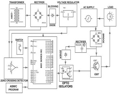
Soft Start of Induction Motor by ACPWM
In this drive, the load is connected in series with the input terminals of the bridge rectifier and its output terminals are connected to the PWM controlled power MOSFET (IGBT or Bipolar or power transistor). If this power transistor is off, then no current flows through the bridge rectifier and thus load remains in the OFF-state. Similarly, if the power transistor is on, then the output terminals of the bridge rectifier gets short circuited and the current flows through the load. As we know that the power transistor can be controlled by the PWM technique. Hence, the load can be controlled by varying the duty cycle of the PWM pulses.
The new control technique of this drive is intended to use in consumer and industrial products ( compressors, washing machines, ventilators) in which there is a need to consider system cost.
Thanks for your interest in learning about motor starter, hope this article given a brief idea regarding the starter role in protecting the motor from high starting currents and to achieve the smooth and soft operation of the induction motor. For any technical help about this article in detail, you are always appreciated for posting your comments in the below comments section.
No comments:
Post a Comment