Showing posts with label Motor. Show all posts

Tuesday, July 12, 2016

Synchronous motor | Types of Synchronous motor

Types of Synchronous motor
There are two major types of synchronous motors depending on how the rotor is magnetized: non-excited and direct-current excited

A- Non-excited motors

In non-excited motors, the rotor is made of steel. At synchronous speed it rotates in step with the rotating magnetic field of the stator, so it has an almost-constant magnetic field through it. The external stator field magnetizes the rotor, inducing the magnetic poles needed to turn it. The rotor is made of a high-retentivity steel such as cobalt steel, These are manufactured in permanent magnet, reluctance and hysteresis designs.

Reluctance motors
These have a rotor consisting of a solid steel casting with projecting (salient) toothed poles. Typically there are fewer rotor than stator poles to minimize torque ripple and to prevent the poles from all aligning simultaneously—a position which cannot generate torque.The size of the air gap in the magnetic circuit and thus the reluctance is minimum when the poles are aligned with the (rotating) magnetic field of the stator, and increases with the angle between them. This creates a torque pulling the rotor into alignment with the nearest pole of the stator field. Thus at synchronous speed the rotor is "locked" to the rotating stator field. This cannot start the motor, so the rotor poles usually have squirrel-cage windings embedded in them, to provide torque below synchronous speed. The machine starts as an induction motor until it approaches synchronous speed, when the rotor "pulls in" and locks to the rotating stator field.
Reluctance motor designs have ratings that range from fractional horsepower (a few watts) to about 22 kW. Very small reluctance motors have low torque, and are generally used for instrumentation applications. Moderate torque, integral horsepower motors use squirrel cage construction with toothed rotors. When used with an adjustable frequency power supply, all motors in the drive system can be controlled at exactly the same speed. The power supply frequency determines motor operating speed.

Hysteresis motors
These have a solid smooth cylindrical rotor, cast of a high coercivity magnetically "hard" cobalt steel.This material has a wide hysteresis loop (high coercivity), meaning once it is magnetized in a given direction, it requires a large reverse magnetic field to reverse the magnetization. The rotating stator field causes each small volume of the rotor to experience a reversing magnetic field. Because of hysteresis the phase of the magnetization lags behind the phase of the applied field. The result of this is that the axis of the magnetic field induced in the rotor lags behind the axis of the stator field by a constant angle δ, producing a torque as the rotor tries to "catch up" with the stator field. As long as the rotor is below synchronous speed, each particle of the rotor experiences a reversing magnetic field at the "slip" frequency which drives it around its hysteresis loop, causing the rotor field to lag and create torque. There is a 2-pole low reluctance bar structure in the rotor. As the rotor approaches synchronous speed and slip goes to zero, this magnetizes and aligns with the stator field, causing the rotor to "lock" to the rotating stator field.
A major advantage of the hysteresis motor is that since the lag angle δ is independent of speed, it develops constant torque from startup to synchronous speed. Therefore, it is self-starting and doesn't need an induction winding to start it, although many designs do have a squirrel-cage conductive winding structure embedded in the rotor to provide extra torque at start-up.
Hysteresis motors are manufactured in sub-fractional horsepower ratings, primarily as servomotors and timing motors. More expensive than the reluctance type, hysteresis motors are used where precise constant speed is required.

Permanent magnet motors
A permanent magnet synchronous motor (PMSM) uses permanent magnets embedded in the steel rotor to create a constant magnetic field. The stator carries windings connected to an AC supply to produce a rotating magnetic field. At synchronous speed the rotor poles lock to the rotating magnetic field. Permanent magnet synchronous motors are similar to brushless DC motors.
Because of the constant magnetic field in the rotor these cannot use induction windings for starting. These motors require a variable-frequency power source to start.
The main difference between a permanent magnet synchronous motor and an asynchronous motor is the rotor. Some studies seem to indicate that NdFeB permanent magnet synchronous motors are around 2 percent more efficient than the highest-efficiency (IE3) asynchronous motors -- using the same stator laminations and similar variable-frequency speed controllers.
Permanent magnet motors have been used as gearless elevator motors since 2000.

B- DC-excited motors


Usually made in larger sizes (larger than about 1 horsepower or 1 kilowatt) these motors require direct current (DC) supplied to the rotor for excitation. This is most straightforwardly supplied through slip rings, but a brushless AC induction and rectifier arrangement may also be used.The direct current may be supplied from a separate DC source or from a DC generator directly connected to the motor shaft.

Synchronous motor

Synchronous Motors
It may be recalled that a d.c. generator can be run as a d.c. motor. In like manner, an alternator may operate as a motor by connecting its armature winding to a 3-phase supply. It is then called a synchronous motor. As the name implies, a synchronous motor runs at synchronous speed (Ns = 120f/P) i.e., in synchronism with the revolving field produced by the 3-phase supply. The speed of rotation is, therefore, tied to the frequency of the source. Since the frequency is fixed, the motor speed stays constant irrespective of the load or voltage of 3- phase supply. However, synchronous motors are not used so much because they run at constant speed (i.e., synchronous speed) but because they possess other unique electrical properties.
A synchronous electric motor is an AC motor in which, at steady state,the rotation of the shaft is synchronized with the frequency of the supply current; the rotation period is exactly equal to an integral number of AC cycles. Synchronous motors contain multiphase AC electromagnets on the stator of the motor that create a magnetic field which rotates in time with the oscillations of the line current. The rotor with permanent magnets or electromagnets turns in step with the stator field at the same rate and as a result, provides the second synchronized rotating magnet field of any AC motor. A synchronous motor is only considered doubly fed if is supplied with independently excited multiphase AC electromagnets on both the rotor and stator.

The synchronous motor and induction motor are the most widely used types of AC motor. The difference between the two types is that the synchronous motor rotates in exact synchronism with the line frequency. The synchronous motor does not rely on current induction to produce the rotor's magnetic field. By contrast, the induction motor requires "slip", the rotor must rotate slightly slower than the AC current alternations, to induce current in the rotor winding. Small synchronous motors are used in timing applications such as in synchronous clocks, timers in appliances, tape recorders and precision servomechanisms in which the motor must operate at a precise speed; speed accuracy is that of the power line frequency, which is carefully controlled in large interconnected grid systems.

Synchronous Motor Working Principle

Synchronous Motors
It may be recalled that a d.c. generator can be run as a d.c. motor. In like manner, an alternator may operate as a motor by connecting its armature winding to a 3-phase supply. It is then called a synchronous motor. As the name implies, a synchronous motor runs at synchronous speed (Ns = 120f/P) i.e., in synchronism with the revolving field produced by the 3-phase supply. The speed of rotation is, therefore, tied to the frequency of the source. Since the frequency is fixed, the motor speed stays constant irrespective of the load or voltage of 3- phase supply. However, synchronous motors are not used so much because they run at constant speed (i.e., synchronous speed) but because they possess other unique electrical properties. In this chapter, we shall discuss the working and characteristics of synchronous motors.
Construction
A synchronous motor is a machine that operates at synchronous speed and converts electrical energy into mechanical energy. It is fundamentally an alternator operated as a motor. Like an alternator, a synchronous motor has the following two parts:
(i) a stator which houses 3-phase armature winding in the slots of the stator core and receives power from a 3-phase supply
 (ii) a rotor that has a set of salient poles excited by direct current to form alternate N and S
poles. The exciting coils are connected in series to two slip rings and direct current is
fed into the winding from an external exciter mounted on the rotor shaft. The stator is wound for the same number of poles as the rotor poles. As in the case of an induction motor, the number of poles determines the synchronous speed of the motor: Synchronous speed, Synchronous speed, Ns=120f/p
where f = frequency of supply in Hz
P = number of poles
An important drawback of a synchronous motor is that it is not self-starting and
auxiliary means have to be used for starting it.

Some salient features of a synchronous motor are:
(i) A synchronous motor runs at synchronous speed or not at all. Its speed is constant (synchronous speed) at all loads. The only way to change its speed is to alter the supply frequency (Ns = 120 f/P).
(ii) The outstanding characteristic of a synchronous motor is that it can be made to operate over a wide range of power factors (lagging, unity or leading) by adjustment of its field excitation. Therefore, a synchronous motor can be made to carry the mechanical load at constant speed and at the same time improve the power factor of the system.
(iii) Synchronous motors are generally of the salient pole type.
(iv) A synchronous motor is not self-starting and an auxiliary means has to be used for starting it. We use either induction motor principle or a separate starting motor for this purpose. If the latter method is used, the machine  must be run up to synchronous speed and synchronized as an alternator.

Operating Principle
The fact that a synchronous motor has no starting torque can be easily explained.
(i) Consider a 3-phase synchronous motor having two rotor poles NR and SR.
Then the stator will also be wound for two poles NS and SS. The motor has
direct voltage applied to the rotor winding and a 3-phase voltage applied to
the stator winding. The stator winding produces a rotating field which
revolves round the stator at synchronous speed Ns(= 120 f/P). The direct (or
zero frequency) current sets up a two-pole field which is stationary so long
as the rotor is not turning. Thus, we have a situation in which there exists a
pair of revolving armature poles (i.e., NS - SS) and a pair of stationary rotor
poles (i.e., NR - SR).
(ii) Suppose at any instant, the stator poles are at positions A and B as shown in Fig.It is clear that poles NS and NR repel each other and so do the poles SS and SR. Therefore, the rotor tends to move in the anticlockwise direction. After a period of half-cycle (or ½ f = 1/100 second),
the polarities of the stator poles are reversed but the polarities of the rotor poles remain the same as shown in Fig. Now SS and NR attract each other and so do NS and SR. Therefore, the rotor tends to move in the clockwise direction. Since the stator poles change their polarities rapidly, they tend to pull the rotor first in one direction and then after a period of
half-cycle in the other. Due to high inertia of the rotor, the motor fails to start.
Hence, a synchronous motor has no self-starting torque i.e., a synchronous motor cannot start by itself. How to get continuous unidirectional torque? If the rotor poles are rotated by
some external means at such a speed that they interchange their positions along with the stator poles, then the rotor will experience a continuous unidirectional torque. This can be understood from the following discussion:
(i) Suppose the stator field is rotating in the clockwise direction and the rotor is also rotated clockwise by some external means at such a speed that the rotor poles interchange their positions along with the stator poles.
(ii) Suppose at any instant the stator and rotor poles are in the position shown in Fig. It is clear that torque on the rotor will be clockwise. After a period of half-cycle, the stator poles reverse their polarities and at the same time rotor poles also interchange their positions as shown in Fig. The result is that again the torque on the rotor is clockwise.
Hence a continuous unidirectional torque acts on the rotor and moves it in the clockwise direction. Under this condition, poles on the rotor always face poles of opposite polarity on the stator and a strong magnetic attraction is set up between them. This mutual attraction locks the rotor and stator together and the rotor is virtually pulled into step with the speed of revolving flux (i.e., synchronous speed).
(iii) If now the external prime mover driving the rotor is removed, the rotor will continue to rotate at synchronous speed in the clockwise direction because the rotor poles are magnetically locked up with the stator poles. It is due to this magnetic interlocking between stator and rotor poles that a synchronous motor runs at the speed of revolving flux i.e., synchronous speed.
Making Synchronous Motor Self-Starting
A synchronous motor cannot start by itself. In order to make the motor self-starting,  a squirrel cage winding (also called damper winding) is provided on the rotor. The damper winding consists of copper bars embedded in the pole faces of the salient poles of the rotor as shown in Fig. The bars are short-circuited at the ends to form in effect a partial squirrel cage winding. The damper winding serves to start the motor.
(i) To start with, 3-phase supply is given to the stator winding while the rotor field winding is left unenergized. The rotating stator field induces currents in the damper or squirrel cage winding and the motor starts as an induction motor.
(ii) As the motor approaches the synchronous speed, the rotor is excited with direct current. Now the resulting poles on the rotor face poles of opposite polarity on the stator and a strong magnetic attraction is set up between them. The rotor poles lock in with the poles of rotating flux. Consequently, the rotor revolves at the same speed as the stator field i.e., at synchronous
speed.
(iii) Because the bars of squirrel cage portion of the rotor now rotate at the same speed as the rotating stator field, these bars do not cut any flux and, therefore, have no induced currents in them. Hence squirrel cage portion of the rotor is, in effect, removed from the operation of the motor. It may be emphasized here that due to magnetic interlocking between the stator
and rotor poles, a synchronous motor can only run at synchronous speed. At any other speed, this magnetic interlocking (i.e., rotor poles facing opposite polarity stator poles) ceases and the average torque becomes zero. Consequently, the motor comes to a halt with a severe disturbance on the line.

Note: It is important to excite the rotor with direct current at the right moment. For example, if the d.c. excitation is applied when N-pole of the stator faces N-pole of the rotor, the resulting magnetic repulsion will produce a violent mechanical shock. The motor will immediately slow down and the circuit breakers will trip. In practice, starters for synchronous motors arc designed to detect the precise moment when excitation should be applied.


Working Principle of Synchronous Motor | Video


Working Principle of Three Phase Induction Motor

Working Principle of Three Phase Induction Motor


The stator of the motor consists of overlapping winding offset by an electrical angle of 120°. When the primary winding or the stator is connected to a 3 phase AC source, it establishes a rotating magnetic field which rotates at the synchronous speed.
 According to Faraday’s law an emf induced in any circuit is due to the rate of change of magnetic flux linkage through the circuit. As the rotor winding in an induction motor are either closed through an external resistance or directly shorted by end ring, and cut the stator rotating magnetic field, an emf is induced in the rotor copper bar and due to this emf a current flows through the rotor conductor. Here the relative speed between the rotating flux and static rotor conductor is the cause of current generation; hence as per Lenz's law the rotor will rotate in the same direction to reduce the cause i.e. the relative velocity.
Thus from the working principle of three phase induction motor it may observed that the rotor speed should not reach the synchronous speed produced by the stator. If the speeds equals, there would be no such relative speed, so no emf induced in the rotor, & no current would be flowing, and therefore no torque would be generated. Consequently the rotor can not reach the synchronous speed. The difference between the stator (synchronous speed) and rotor speeds is called the slip. The rotation of the magnetic field in an induction motor has the advantage that no electrical connections need to be made to the rotor.

Working Principle of Three Phase Induction Motor| Video


Starting methods of three phase induction motors

Starting methods of three phase induction motors

A 3-phase induction motor is theoretically self starting. The stator of an induction motor consists of 3-phase windings,which when connected to a 3-phase supply creates a rotating magnetic field. This will link and cut the rotor conductors which in turn will induce a current in the rotor conductors and create a rotor magnetic field. The magnetic field created by the rotor will interact with the rotating magnetic field in the stator and produce rotation.Therefore, 3-phase induction motors employ a starting method not to provide a starting torque at the rotor, but because of the following reasons;
1) Reduce heavy starting currents and prevent motor from overheating.
2) Provide overload and no-voltage protection.
There are many methods in use to start 3-phase induction motors. Some of the common methods are;
1- Direct On-Line Starter (DOL)
2- Star-Delta Starter
3- Auto Transformer Starter
4- Rotor Impedance Starter
5- Power Electronics Starter

Direct On-Line Starter (DOL)
The Direct On-Line (DOL) starter is the simplest and the most inexpensive of all starting methods and is usually used for squirrel cage induction motors. It directly connects the contacts of the motor to the full supply voltage. The starting current is very large, normally 6 to 8 times the rated current. The starting torque is likely to be 0.75 to 2 times the full load torque. In order to avoid excessive voltage drops in the supply line due to high starting currents, the DOL starter is used only for motors with a rating of less than 5KW.There are safety mechanisms inside the DOL starter which provides protection to the motor as well as the operator of the motor.The power and control circuits of induction motor with DOL starter are shown in figure.


Star-Delta Starter
The star delta starting is a very common type of starter and extensively used, compared to the other types of the starters. This method used reduced supply voltage in starting.
The method achieved low starting current by first connecting the stator winding in star configuration, and then after the motor reaches a certain speed, throw switch changes the winding arrangements from star to delta configuration. By connecting the stator windings, first in star and then in delta, the line current drawn by the motor at starting is reduced to one-third as compared to starting current with the windings connected in delta. At the time of starting when the stator windings are start connected, each stator phase gets voltage. Since the torque developed by an induction motor is proportional to the square of the applied voltage, star- delta starting reduced the starting torque to one – third that obtainable by direct delta starting.


Auto Transformer Starter
The operation principle of auto transformer method is similar to the star delta starter method. The starting current is limited by (using a three phase auto transformer) reduce the initial stator applied voltage.The auto transformer starter is more expensive, more complicated in operation and bulkier in construction when compared with the star – delta starter method. But an auto transformer starter is suitable for both star and delta connected motors, and the starting current and torque can be adjusted to a desired value by taking the correct tapping from the auto transformer. When the star delta method is considered, voltage can be adjusted only by
factor of 1/√3.


Starting Methods of Single Phase Motor

Starting Methods of Single Phase Motor

There are different methods to start the 1-ϕ motors, they are as follows:

1- Split Phase or Resistance Start
2- Capacitor Start
3- Permanent Split Capacitor
4- Capacitor Start Capacitor Run

5- Electronic Starter for Single Phase Motor


Resistance start motor
A resistance start motor is a split-phase induction motor with a starter inserted in series with the startup winding, creating reactance. This added starter provides assistance in the starting and initial direction of rotation.

Capacitor start motor

Schematic of a capacitor start motor.
A capacitor start motor is a split-phase induction motor with a starting capacitor inserted in series with the startup winding, creating an LC circuit which produces a greater phase shift (and so, a much greater starting torque) than both split-phase and shaded pole motors.

Permanent-split capacitor motor
Another variation is the permanent-split capacitor (or PSC) motor.Also known as a capacitor-run motor, this type of motor uses a non-polarized capacitor with a high voltage rating to generate an electrical phase shift between the run and start windings. PSC motors are the dominant type of split-phase motor in Europe and much of the world, but in North America, they are most frequently used in variable torque applications (like blowers, fans, and pumps) and other cases where variable speeds are desired
.

A capacitor with a relatively low capacitance, and relatively high voltage rating, is connected in series with the start winding and remains in the circuit during the entire run cycle.Like other split-phase motors, the main winding is used with a smaller start winding, and rotation is changed by reversing the connection between the main winding and the start circuit. There are significant differences, however; the use of a speed sensitive centrifugal switch requires that other split-phase motors must operate at, or very close to, full speed. PSC motors may operate within a wide range of speeds, much lower than the motor's electrical speed. Also, for applications like automatic door openers that require the motor to reverse rotation often, the use of a mechanism requires that a motor must slow to a near stop before contact with the start winding is re-established. The 'permanent' connection to the capacitor in a PSC motor means that changing rotation is instantaneous.
Three-phase motors can be converted to PSC motors by making common two windings and connecting the third via a capacitor to act as a start winding. However, the power rating needs to be at least 50% larger than for a comparable single-phase motor due to an unused winding.
Capacitor start - capacitor run induction motor


A Capacitor Start Motor not only switches out the capacitor when up to speed, but also switches out the starting winding which is in series with the start capacitor. Capacitor Start motors have very high starting torque for a single phase AC motor. The same is true for a capacitor start / capacitor run motor with a centrifugal switch. In this case, the run capacitor is a different value and just provides some additional phase lag especially to help the motor maintain speed under load, and improve the power factor. A Capacitor start/run motor without a centrifugal switch has a lower starting torque, but good performance under load, and again, an improved power factor.

Protection Scheme of Single phase Induction Motor

The starter is a device which is used for switching and protecting the electric motor from the dangerous overloads by tripping. It reduces the starting current to the AC induction motors and also reduces the motor torque.

Electronic Starter Circuit Working

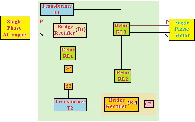
Electronic starter is used for motor protection from overload and short-circuit conditions. A current sensor in the circuit is used to limit the current drawn by the motor because in a few cases such as failure of the bearing, pump defect or any other reason, the current drawn by the motor exceeds its normal rated current. In these conditions the current sensor trips the circuit for protecting the motor. The electronic starter for the motor circuit block diagram is shown below.
Electronic Starter Circuit
Electronic Starter Circuiy
Switch S1 is used for switching ON the supply through transformer T2 and N/C contacts of the relay RL1. The DC voltage developed across the capacitor C2 through the bridge rectifier will energize the relay RL2. With the energization of the relay RL2, the voltage developed across the C2 energizes the relay RL3 and thus, supply is given to the motor. If the motor draws overcurrent, then the voltage developed across the secondary of the transformerT2 energizes the relay RL1 to trip the relays RL2 and RL3.

Soft Start of Induction Motor by ACPWM

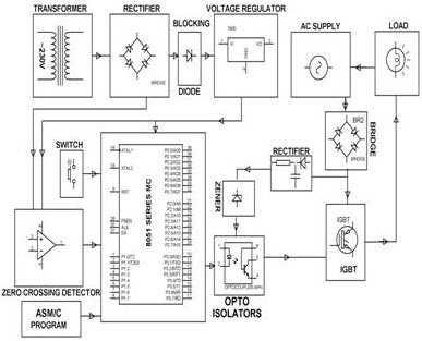
The proposed system is intended to offer soft start of the single phase induction motor using a PWM sinusoidal voltage while starting the motor. This system avoids the frequently used TRIAC-phase-angle control drives and provides variable AC voltage during the starting of the single phase induction motor. Similar to the TRIAC control method, the voltage is varied from zero to maximum during the start in a very small span of time.
As, in this technique we use the PWM technique   that produces much lower high order harmonics. In this project, the mains AC voltage is directly modulated using a very less number of active and passive power components. Hence, it does not require any converter topology and costly conventional converters to produce output voltage waveforms. A single- phase- motor starter wiring diagram is shown in the below figure.
Soft Start of Induction Motor by ACPWM
In this drive, the load is connected in series with the input terminals of the bridge rectifier and its output terminals are connected to the PWM controlled power MOSFET (IGBT or Bipolar or power transistor). If this power transistor is off, then no current flows through the bridge rectifier and thus load remains in the OFF-state. Similarly, if  the power transistor is on, then the output terminals of the bridge rectifier gets short circuited and the current flows through the load. As we know that the power transistor can be controlled by the PWM technique. Hence, the load can be controlled by varying the duty cycle of the PWM pulses.
The new control technique of this drive is intended to use in consumer and industrial products ( compressors, washing machines, ventilators) in which there is a need to consider system cost.
Thanks for your interest in learning about motor starter, hope this article given a brief idea regarding the starter role in protecting the motor from high starting currents and to achieve the smooth and soft operation of the induction motor. For any technical help about this article in detail, you are always appreciated for posting your comments in the below comments section.

Single Phase Induction Motor

Single Phase Induction Motor

  • Single-phase induction motors are not self-starting without an auxiliary stator winding driven by an out of phase current of near 90 degree. Once started the auxiliary winding is optional.
    The auxiliary winding of a permanent-split capacitor motor has a capacitor in series with it during starting and running.
    A capacitor-start induction motor only has a capacitor in series with the auxiliary winding during starting.
    A capacitor-run motor typically has a large non-polarized electrolytic capacitor in series with the auxiliary winding for starting, then a smaller non-electrolytic capacitor during running.
    The auxiliary winding of a resistance split-phase motor develops a phase difference versus the main winding during starting by virtue of the difference in resistance.


Types of Single Phase Induction Motor

Types of Induction Motor


 A- SINGLE PHASE INDUCTION MOTOR

       1-  Split phase induction motor
       2- Capacitor start induction motor
       3- Capacitor start capacitor run induction motor
       4- Shaded pole induction motor

 B-  THREE PHASE INDUCTION MOTOR

       1- Squirrel cage induction motor
       2- Slip ring induction motor

A- SINGLE PHASE INDUCTION MOTOR
Often focus is on basic knowledge of three-phase motors. This is partly because Grundfos sells
far more three-phase motors than single-phase motors. Grundfos does, however, also manufacture
single-phase motors up to 2.2 kw 2-pole and 1.5 kW 4-pole. Single-phase motors work on the
same principles as three-phase motors, but have lower starting torques and need help to start. The
various motor types are defined by the starting method used. A standard single-phase stator has two windings placed at an angle of 90° to each other. One of these windings is known as the main winding, while the other is called the auxiliary winding or starting winding. Depending on the number of poles, each winding may be distributed across several subcoils.

Split-phase motor

Another common single-phase AC motor is the split-phase induction motor, commonly used in major appliances such as air conditioners and clothes dryers. Compared to the shaded pole motor, these motors provide much greater starting torque.

A split-phase motor has a secondary startup winding that is 90 electrical degrees to the main winding, always centered directly between the poles of the main winding, and connected to the main winding by a set of electrical contacts. The coils of this winding are wound with fewer turns of smaller wire than the main winding, so it has a lower inductance and higher resistance. The position of the winding creates a small phase shift between the flux of the main winding and the flux of the starting winding, causing the rotor to rotate. When the speed of the motor is sufficient to overcome the inertia of the load, the contacts are opened automatically by a centrifugal switch or electric relay. The direction of rotation is determined by the connection between the main winding and the start circuit. In applications where the motor requires a fixed rotation, one end of the start circuit is permanently connected to the main winding, with the contacts making the connection at the other end.
Capacitor start motor

Schematic of a capacitor start motor.
A capacitor start motor is a split-phase induction motor with a starting capacitor inserted in series with the startup winding, creating an LC circuit which produces a greater phase shift (and so, a much greater starting torque) than both split-phase and shaded pole motors.

Capacitor start capacitor run induction motor


A Capacitor Start Motor not only switches out the capacitor when up to speed, but also switches out the starting winding which is in series with the start capacitor. Capacitor Start motors have very high starting torque for a single phase AC motor. The same is true for a capacitor start / capacitor run motor with a centrifugal switch. In this case, the run capacitor is a different value and just provides some additional phase lag especially to help the motor maintain speed under load, and improve the power factor. A Capacitor start/run motor without a centrifugal switch has a lower starting torque, but good performance under load, and again, an improved power factor.
Resistance start motor
A resistance start motor is a split-phase induction motor with a starter inserted in series with the startup winding, creating reactance. This added starter provides assistance in the starting and initial direction of rotation.

Permanent-split capacitor motor
Another variation is the permanent-split capacitor (or PSC) motor.Also known as a capacitor-run motor, this type of motor uses a non-polarized capacitor with a high voltage rating to generate an electrical phase shift between the run and start windings. PSC motors are the dominant type of split-phase motor in Europe and much of the world, but in North America, they are most frequently used in variable torque applications (like blowers, fans, and pumps) and other cases where variable speeds are desired.

A capacitor with a relatively low capacitance, and relatively high voltage rating, is connected in series with the start winding and remains in the circuit during the entire run cycle.Like other split-phase motors, the main winding is used with a smaller start winding, and rotation is changed by reversing the connection between the main winding and the start circuit. There are significant differences, however; the use of a speed sensitive centrifugal switch requires that other split-phase motors must operate at, or very close to, full speed. PSC motors may operate within a wide range of speeds, much lower than the motor's electrical speed. Also, for applications like automatic door openers that require the motor to reverse rotation often, the use of a mechanism requires that a motor must slow to a near stop before contact with the start winding is re-established. The 'permanent' connection to the capacitor in a PSC motor means that changing rotation is instantaneous.
Three-phase motors can be converted to PSC motors by making common two windings and connecting the third via a capacitor to act as a start winding. However, the power rating needs to be at least 50% larger than for a comparable single-phase motor due to an unused winding.

Shaded-Pole Motor is the original type of AC single-phase induction motor. A shaded-pole motor is a small squirrel-cage motor in which the auxiliary winding is composed of a copper ring or bar surrounding a portion of each pole.This auxiliary single-turn winding is called a shading coil. Currents induced in this coil by the magnetic field create a second electrical phase by delaying the phase of magnetic flux change for that pole (a shaded pole) enough to provide a 2-phase rotating magnetic field. The direction of rotation is from the unshaded side to the shaded (ring) side of the pole.Since the phase angle between the shaded and unshaded sections is small, shaded pole motors produce only a small starting torque relative to torque at full speed. Shaded-pole motors of the asymmetrical type shown are only reversible via disassembly and flipping over the stator, though some similar-looking motors have small, switch-shortable auxiliary windings of thin wire instead of thick copper bars and can reverse electrically. Another method of electrical reversing involves four coils (two pairs of identical coils).

The common, asymmetrical form of these motors (pictured) has only one winding, with no capacitor or starting windings/starting switch, making them economical and reliable. Larger and more modern types may have multiple physical windings, though electrically only one, and a capacitor may be used. Because their starting torque is low, they are best suited to driving fans or other loads that are easily started. They may have multiple taps near one electrical end of the winding, which provides variable speed and power via selection of one tap at a time, as in ceiling fans. Moreover, they are compatible with TRIAC-based variable-speed controls, which often are used with fans. They are built in power sizes up to about 1⁄4 horsepower (190 W) output. Above 1⁄3 horsepower (250 W), they are not common, and for larger motors, other designs offer better characteristics.

Monday, July 11, 2016

Types of Three Phase Induction Motor

Types of Induction Motor

 A- SINGLE PHASE INDUCTION MOTOR

       1-  Split phase induction motor
       2- Capacitor start induction motor
       3- Capacitor start capacitor run induction motor
       4- Shaded pole induction motor

 B-  THREE PHASE INDUCTION MOTOR

       1- Squirrel cage induction motor
       2- Slip ring induction motor

 B-  THREE PHASE INDUCTION MOTOR
Construction Of Squirrel Cage Induction Motor
Any Induction Motor has a Stator and a Rotor. The construction of Stator for any induction motor is almost the same. But the rotor construction differs with respect to the type which is specified above.

STATOR:
The stator is the outer most component in the motor which can be seen. It may be constructed for single phase, three phase or even poly phase motors. But basically only the windings on the stator vary, not the basic layout of the stator. It is almost same for any given synchronous motor or a generator. It is made up of number of stampings, which are slotted to receive the windings. Lets see the construction of a three phase stator. The three phase windings are placed on the slots of laminated core and these windings are electrically spaced 120 degrees apart. These windings are connected as either star or delta depending upon the requirement. The leads are taken out usually three in number, brought out to the terminal box mounted on the motor frame. The insulation between the windings are generally varnish or oxide coated.
 Squirrel Cage Rotor:
This kind of rotor consists of a cylindrical laminated core with parallel slots for carrying the rotor conductors, which are not wires, as we think, but thick, heavy bars of copper or aluminium (aluminium) or its alloys. The conductor bars are inserted from one end of the rotor and as one bar in each slot. There are end rings which are welded or electrically braced or even bolted at both ends of the rotor, thus maintaining electrical continuity. These end rings are short-circuited, after which they give a beautiful look similar to a squirrel thus the name.
One important point to be noted is that the end rings and the rotor conducting bars are permanently short-circuited, thus it is not possible to add any external resistance in series with the rotor circuit for starting purpose. The rotor conducting bars are usually not parallel to the shaft, but are purposely given slight skew. In small motors, the rotor is fabricated in a different way. The entire rotor core is placed in a mould and the rotor bars & end-rings are cast into one piece. The metal commonly used is aluminium alloy. Some very small rotors which operate on the basis of eddy current, have their rotor as solid steel without any conductors.


Reasons for Having Skewed Rotor
1. It helps in reduction of magnetic hum, thus keeping the motor quiet,
2. It also helps to avoid “Cogging", i.e. locking tendency of the rotor. The tendency of rotor   teeth remaining under the stator teeth due to the direct magnetic attraction between the two.
3. Increase in effective ratio of transformation between stator & rotor,
4. Increased rotor resistance due to comparatively lengthier rotor conductor bars, &
5. Increased slip for a given torque.
As 95% of the motors used are of Squirrel cage type, they have been classed under 6 different Categories. These categorization is based on the electrical characteristics of the rotor and its construction. Know these different classes and appreciate each and every individual characteristics of these classes. Also check out what came up to over come the poor starting torque of squirrel cage induction motor.Know about the construction of Double Squirrel cage motor with a graphical comparison with single cage.
Double Squirrel Cage Motor
We have already discussed that the rotor which is of squirrel cage type has two end rings, which are permanently shorted with the rotor conductors. Thus external resistance could not be added to the rotor circuit. Since the rotor has a very low resistance, the starting torque was very poor. The starting torque could be increased by having a cage of high resistance, but the motor will have a very poor efficiency during normal running conditions, as there will be more Cu losses. So Mr. Boucheort, came up with a motor, which had two independent cages on the same rotor. The outer cage consists of bars of high resistance metal, whereas the inner cage has low-resistance copper bars. Thus the outer cage has a high resistance with low reactance to resistance ratio and the inner cage has low resistance but high reactance to resistance ratio. Thus the outer cage develops a maximum torque at starting, while the inner cage does so at about 15% slip.
Slip-Ring Induction Motor
Stator:
The construction of a stator is the same for both the squirrel cage and slip ring induction motor. The main difference in a slip ring induction motor is on the rotor construction and usage. Some changes in the stator may be encountered when a slip ring motor is used in a cascaded system, as the supply for the slave motor is controlled by the supply from the rotor of the other slip ring motor with external resistance mounted on its rotor.
Rotor:
he slip ring induction motors usually have a “Phase-Wound" rotor. This type of rotor is provided with a 3-phase, double-layer, distributed winding consisting of coils used in alternators. The rotor core is made up of steel laminations which have slots to accommodate formed 3-single phase windings. These windings are placed 120 degrees electrically apart.
The rotor is wound for as many poles as the number in the stator and is always 3-phase, even though the stator is wound for 2-phase. These three windings are “starred" internally and the other end of these three windings are brought out and connected to three insulated slip-rings mounted on the rotor shaft itself. The three terminal ends touch these three slip rings with the help of carbon brushes which are held against the rings with the help of a spring assembly.

What happens when external resistance is added?
In the case of a squirrel cage induction motor, the rotor resistance is very low so that the current in the rotor is high, which makes its starting torque poor. But adding external resistance, as in the case of a slip ring induction motor, makes the rotor resistance high when starting, thus the rotor current is low and the starting torque is maximum. Also the slip necessary to generate maximum torque is directly proportional to the rotor resistance. In slip ring motors, the rotor resistance is increased by adding external resistance, so the slip is increased. Since the rotor resistance is high, the slip is more, thus it's possible to achieve “pull-out" torque even at low speeds. As the motor reaches its base speed (full rated speed), after the removal of external resistance and under normal running conditions, it behaves in the same way as a squirrel cage induction motor.
Thus these motors are best suited for very high inertia loads, which requires a pull-out torque at almost zero speed and acceleration to full speed with minimum current drawn in a very short time period.
Advantages of slip ring induction motors
The main advantage of a slip ring induction motor is that its speed can be controlled easily.
"Pull-out torque" can be achieved even from zero RPM.
It has a high starting torque when compared to squirrel cage induction motor. Approximately 200 - 250% of its full-load torque.
A squirrel cage induction motor takes 600% to 700% of the full load current, but a slip ring induction motor takes a very low starting current approximately 250% to 350% of the full load current.